Structurally, it differs from a voltage-source inverter: instead of each switching device being connected in parallel with a freewheeling diode, a current-type inverter places a reverse-blocking diode in series with each switching device. They are essential in several applications, including as power distribution networks, renewable energy systems, and. . These devices change direct current (DC) from batteries or panels into alternating current (AC) split across three phases for better efficiency. This is especially useful in systems like a 220v 3 phase inverter, which handles everyday voltage needs. Both of them are used for conversion from DC to AC. Line-to-line voltage at the load is maintained at 4. in this topology, gate signals are applied at 60-degree intervals to the power switches, creating the required 3-phase AC signal.
[PDF Version]
From the late nineteenth century through the middle of the twentieth century, DC-to-AC was accomplished using or sets (M–G sets). In the early twentieth century, and began to be used as switches in inverter circuits. The most widely used type of tube was the .
[PDF Version]
Think of your solar array as a water supply system - voltage acts like water pressure, while current represents the flow rate. Both must work in harmony to power your devices effectively. . Understanding how current and voltage work in inverters could mean the difference between optimal energy harvest and system failure in your solar project. When designing solar power systems, engineers often face a critical choice: should they prioritize voltage compatibility or current handling. . The relationship between current (I I) and voltage (V V) in most electrical circuits is described by Ohm's Law: I = V RI = RV I = V R I = R V Key Points: Current is directly proportional to voltage: If resistance is constant, increasing voltage increases current. Current is inversely proportional. . Inverter input is a resource that enters the inverter in the form of direct current (DC) supplied from DC sources such as batteries, solar panels, PV, wind turbines, or other DC sources to be converted into alternating current (AC). What peak current would I then expect through the switches? For the purposes of this calculation, we. .
[PDF Version]
VSI structure comes with different electronic components such as an IGBT inverter, MOSFET transistor, PWM circuit, and filter circuits. DC sources provide stable DC voltages for performing. . An inverter is the main part of electronic circuit projects that convert DC power to AC through the following solid-state circuits. This conversion is critical in diverse programs, inclusive of renewable power structures, uninterruptible strength materials (UPS), and electric-powered automobile powertrains. The. . In the domain of power electronics and electrical engineering, the Voltage Source Inverter (VSI) stands as a pivotal technology for converting direct current (DC) into alternating current (AC) with controllable voltage and frequency.
[PDF Version]
The voltage from each panel adds up along the line, while the current remains constant. This configuration allows the string solar inverter to receive a higher voltage DC input, making the conversion to AC more efficient. It's a bit like several batteries connected end-to-end to. . This article provides a comprehensive analysis of voltage and current calculations for different solar panel configurations, including series, parallel, and hybrid arrangements.
[PDF Version]
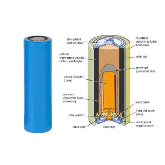
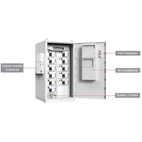
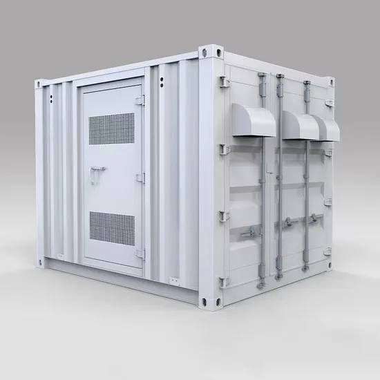
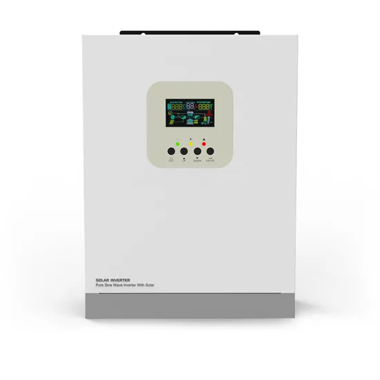
Off-grid inverters must output a stable voltage within specific tolerances to ensure consistent energy delivery: At stable operation, voltage fluctuations should remain within ±5% of the rated voltage. . Learn how to maximize off-grid inverter efficiency for solar power with insights on voltage stability, overload capacity, and safety features. With its MPPT-based high-efficiency solar charge controller, it ensures maximum energy conversion from solar panels while also supporting grid charging when needed. Spanning from 4KW to 12KW, this series stands out with its robust Dual MPPT technology (on 6. 2KW+ models) and High PV Input Voltage (500V), enabling massive. . The battery cluster consists of modules connected in series, and the whole battery system is controlled by BCM to monitor the cluster voltage and current in real time. The battery module consists of LiFePo4 battery cells. As energy independence becomes increasingly important in 2025, understanding how to select. . g profile at 20 °C. For enhanced per-formance and for systems ≥ 48 V we recommend IUI charging to reach 3 dry charged version. ** Filled and charged cell weights +/- 5% *** Acid d .
[PDF Version]