on instructions for LONGi Solar PV modules. It discusses module identification, electrical and mechanical installation requirements, safety precautions, site s. This manual elaborates on installation and safety use information for PV power gener-ating modules (hereinafter referred to as module) of LONGi Solar Technology Co. (hereinafter referred to as LONGi). Please abide by all safety precautions in this guide and local regulations. LONGi reserves the right of final interpretation. (20241118 BGV02 Draft) . leading manufacturer of cost-effective, high efficiency and good quality photovoltaic panel, inverter, battery, controller, solar systemand solar pump system. . echnology delivers superior module effic fications included in this datasheet are subject to change without .
[PDF Version]
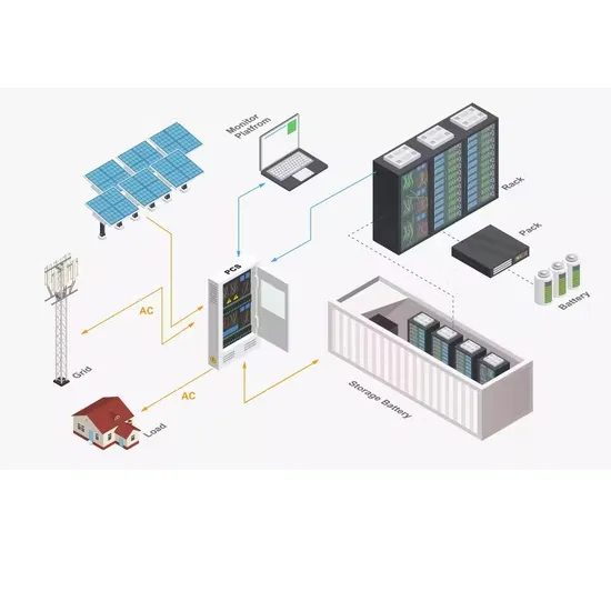
Illustration of waterproofing method for photovol through roofing material,making any roof vulnerable to water intrusion. Given this reality,it's important to understand how water intrusion (and the resulting b ilding damage) occurs and ways installers can pr. em (e. a screw and a metal or plastic washer). The fastening sys profile on the roof is done by hot air welding. Consider the roof type (material and slope), weatherproo ing, installation convenience, and wind and snow loadings. Space requirements and layout for photovoltaic and solar water heating system component should be taken into account early in the design process ng roofing system to maintain its. . Tesla's power producing photovoltaic (PV) roofing Tiles are visually indistinguishable from the non-power producing metal or glass roofing Tiles, enabling homeowners the ability to harvest solar energy without aesthetic compromise. The New Home Design and Construction Guide is published by Tesla. . The present invention relates to a construction method for a waterproof photovoltaic integrated roof, comprising the following steps: mounting a prefabricated concrete roof laminated plate to form a base layer containing a rib plate in the circumferential direction; mounting a photovoltaic support. .
[PDF Version]

2 is an electrical block diagram that illustrates how PV current-voltage measurements are made. A four-wire (or Kelvin) connection to the device under test allows the voltage across the device to be measured by avoiding voltage drops along the wiring in the current measurement. . g energy production and ensuring system stability. Proper installation techniques, including secure mounting and alignment, are essential to optimize the pe formance and longevity of your solar e an essential componentin a rooftop solar system. As the industry has expanded rapidly in recent. . The measurement of photovoltaic (PV) performance with respect to reference conditions requires measuring current versus voltage for a given tabular reference spectrum, junction temperature, and total irradiance. This report presents the procedures implemented by the PV Cell and Module Performance. . Fraunhofer ISE CalLab PV Cells has been accredited as a calibration lab with the “Deutsche Akkreditierungsstelle GmbH” DAkkS (Registration number: D-K-11140-01-00), according to ISO 17025 since 2008 (former DKD). This comprehensive process involves systematic testing, verification, and documentation to ensure your solar PV system operates safely. .
[PDF Version]
Figure 1: Solar cell diagram illustrating the working principle based on the photovoltaic effect. Figure 1 shows a schematic layout of a p-n junction based solar cell. Here the n-region is heavily doped and the n-region is made thin so that maximum sun light can penetrate. . Solar Cell Definition: A solar cell (also known as a photovoltaic cell) is an electrical device that transforms light energy directly into electrical energy using the photovoltaic effect. Working Principle: The working of solar cells involves light photons creating electron-hole pairs at the p-n. . A clear solar power plant diagram helps explain the structure and function of each component that makes up a solar energy system. It is renewable and therefore it is a “Green” source of energy. Construction: Made of silicon with metal contacts and an anti-reflective coating. This energy can be used to generate electricity or be stored in batteries or thermal storage.
[PDF Version]
Here's exactly when to use each configuration, with clear diagrams showing how to wire your panels correctly. "Should I wire my solar panels in series or parallel?" It's the question every DIY solar installer asks, and the wrong answer can cost you efficiency, money. . Voltage Calculation is Critical for Safety: Series wiring adds voltages together, and temperature variations can push systems beyond safe limits. The short answer:. . The single most important tool in your arsenal is a solar panel wiring diagram. This is your non-negotiable blueprint, a detailed map that ensures every component works together safely and efficiently. Learning how to wire solar panels requires learning key concepts, choosing the right inverter, planning the configuration for the system, learning how to do the wiring, and more. Such a connection of modules in a series and parallel combination is known as “Solar Photovoltaic Array” or. .
[PDF Version]
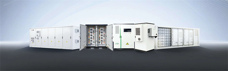
In this video, we explain the working principle of a grid-connected rooftop solar power plant using a simple block diagram. It covers system configurations, components, standards such as UL 1741, battery backup options, inverter sizing, and microinverter systems. Additionally, it touches on utility. . In the basic scheme of an on-grid PV solar system, it must have the following parts: An array of solar panels to transform solar radiation into electrical energy. A solar inverter that transforms the DC power generated by the solar array panels into AC power. We cover the complete power flow from solar PV modules to the. . Next, we will introduce the photovoltaic AC combiner box from aspects such as product function introduction, product display, technical parameters, wiring schematic diagram, installation tools, installation precautions, and wiring, aiming to let photovoltaic people understand the combiner box. . Here are design tips for methods of PV system utility interconnection.
[PDF Version]