The 3-phase bridge comprises 3 half-bridge legs (one for each phase; a, b, c). The devices are often traditionally numbered as illustrated (Conveying conduction order in “square wave” or “six step” operation, as is done for rectifers. ). This article outlines the definition and working principle of three phase bridge inverter. A three phase bridge inverter is a device which converts DC power input. . In particular, considering “full-bridge” structures, half of the devices become redundant, and we can realize a 3-phase bridge inverter using only six switches (three half-bridge legs). ) Current Assignee (The listed assignees may be inaccurate. Each pair of thyristors in. . A three-phase inverter is a type of power electronic device that converts DC (Direct Current) power into AC (Alternating Current) power with three phases. It is widely used in various applications such as motor drives, renewable energy systems, and power transmission.
[PDF Version]
An open circuit test can be performed to measure the open circuit voltage of the module or the string. The test requires a DC voltage meter, and it helps to detect intermittent connection issues or open sub-circuits inside the module (such as diodes or solder traces). It does not cover TS4-specific testing. IMPORTANT: While most of these tests are commonly used in array fault localization and troubleshooting, some cannot be performed with. . Every inverter, especially those used for solar inverter testing, EV inverter testing, or solar PV inverter testing, must meet precise performance and protection standards. Testing identifies electrical stability, waveform accuracy, and thermal reliability, guaranteeing long-term operation. A clamp meter is also needed, which allows for measuring DC current without breaking the circuit, a far safer method than using a. . For technicians who are working on photovoltaic (PV) systems, it is critical to measure and document voltage and confirm polarity. These measurements enable technicians to assess the potential for current flow and identify potential shock hazards.
[PDF Version]
These circuits are overvoltage, overcurrent, short circuit, reverse polarity, temperature, anti-islanding, open-phase, phase-reversal, and lightning or surge protection. Each circuit helps keep the inverter safe. . Meta description: Discover how photovoltaic three-phase inverter protection circuits prevent system failures. Explore cutting-edge solutions, industry trends, and real-world case studies to optimize your solar power setup. The UCC23513 gate driver used has a 6-pin wide body package with optical. . installation conditions specific to every application. Protective and isolating switchgear equipment is particularly important and ABB offers a full range of these products both for circuits branched from photovoltaic panels, where the high direct voltages typical of these installations are. . Eaton offers the industry's most complete and reliable circuit protection for PV balance of system, from fuses, fuse holders and circuit breakers to safety switches and surge protection—allowing for comprehensive overcurrent and overvoltage protection anywhere in the PV system. This article will explore. .
[PDF Version]

This technical information is intended to provide characteristic values of the short-circuit currents of each SMA PV inverter resulting from testing activities in accordance with international standards, and to indicate the difference between the short-circuit . . This technical information is intended to provide characteristic values of the short-circuit currents of each SMA PV inverter resulting from testing activities in accordance with international standards, and to indicate the difference between the short-circuit . . provides characteristic values for the short-circuit currents of individual PV and battery inverters from SMA that result from testing according to international standards. provides information on the difference between the short-circuit current contribution by a conventional power generator and a. . X”d, X'd, Xd, X2 are only meaningful for a single inverter operating point and one single fault location! Danger! : Underestimation of fault current contribution is possible with Thevenin representation when impedance is not changed to adapt to fault location 1. None (far most common) What to do?. nous resources1. circuit involvement is frequently limited to zero and hree In spite of various benefits, the solar PV inverters has times rated current output. The short circuit strength will its own drawbacks as it is static load. 3, May 2025 – Updates to Inom (A) of all inverter models.
[PDF Version]
The invention provides an AC current filtering and sampling circuit of a photovoltaic inverter. . This application note presents a detailed solution for implementing a 3-phase solar inverter application system based on the TMS320F28035 microcontrollers (MCUs). The solution design includes bidirectional 3-phase DC-AC algorithms, and the maximum power point tracking (MPPT) DC-DC algorithm for. . Improvements in design, technology and manufacturing of PV inverters, as well as cost reduction and high efficiency, are always the main objectives, [see References 1, 2]. The short circuit strength will its own drawbacks as it is static load. The conversion process involves two key stages: DC-to-AC inversion and synchronization with the grid's voltage. .
[PDF Version]
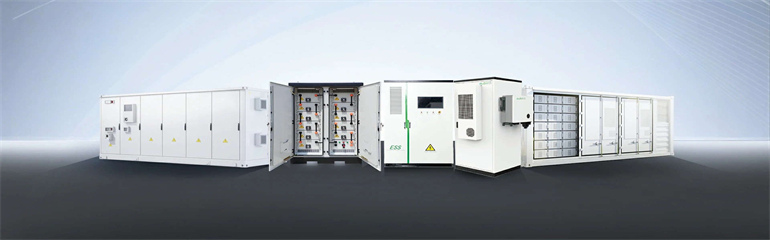
Price and other details may vary based on product size and color. Need help?. Single-phase inverters convert DC power from solar panels into AC electricity compatible with standard residential electrical services, representing the backbone of nearly all U. For installers working with 120/240V split-phase systems, understanding specific. . When residential systems are being set up, the string inverter is generally preferred as it is cost-effective. Please select the company you'd like to login to to continue: . Check each product page for other buying options. If you are very urgent to get the price, please call us or tell us in your email so that we will regard your inquiry priority.
[PDF Version]