The CD4047IC integrated Circuit is connected and set up as an astable multivibrator in this solar inverter circuit. When the SPST switch is turned ON, the Circuit begins to oscillate. The secondary wi.
[PDF Version]

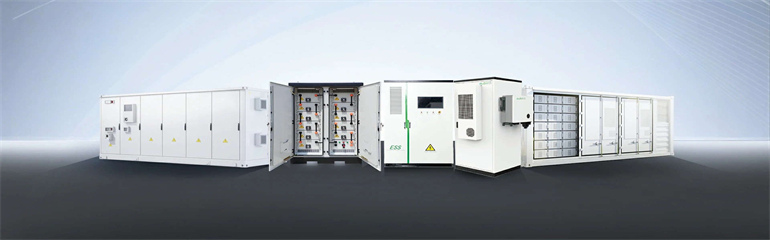
This technical information is intended to provide characteristic values of the short-circuit currents of each SMA PV inverter resulting from testing activities in accordance with international standards, and to indicate the difference between the short-circuit . . This technical information is intended to provide characteristic values of the short-circuit currents of each SMA PV inverter resulting from testing activities in accordance with international standards, and to indicate the difference between the short-circuit . . provides characteristic values for the short-circuit currents of individual PV and battery inverters from SMA that result from testing according to international standards. provides information on the difference between the short-circuit current contribution by a conventional power generator and a. . X”d, X'd, Xd, X2 are only meaningful for a single inverter operating point and one single fault location! Danger! : Underestimation of fault current contribution is possible with Thevenin representation when impedance is not changed to adapt to fault location 1. None (far most common) What to do?. nous resources1. circuit involvement is frequently limited to zero and hree In spite of various benefits, the solar PV inverters has times rated current output. The short circuit strength will its own drawbacks as it is static load. 3, May 2025 – Updates to Inom (A) of all inverter models.
[PDF Version]
These circuits are overvoltage, overcurrent, short circuit, reverse polarity, temperature, anti-islanding, open-phase, phase-reversal, and lightning or surge protection. Each circuit helps keep the inverter safe. . Meta description: Discover how photovoltaic three-phase inverter protection circuits prevent system failures. Explore cutting-edge solutions, industry trends, and real-world case studies to optimize your solar power setup. The UCC23513 gate driver used has a 6-pin wide body package with optical. . installation conditions specific to every application. Protective and isolating switchgear equipment is particularly important and ABB offers a full range of these products both for circuits branched from photovoltaic panels, where the high direct voltages typical of these installations are. . Eaton offers the industry's most complete and reliable circuit protection for PV balance of system, from fuses, fuse holders and circuit breakers to safety switches and surge protection—allowing for comprehensive overcurrent and overvoltage protection anywhere in the PV system. This article will explore. .
[PDF Version]
This guide breaks down the most common solar inverter problems and shows you how to identify, fix, and prevent them step by step. From portable units to all-in-one systems and full home setups, you'll get clear insights to keep your solar power running strong. . Monitor your solar inverter's error codes and display indicators daily – these warning signs often reveal developing issues before complete system failure occurs. Test DC voltage inputs and AC outputs using a multimeter when your system's performance drops, ensuring readings match manufacturer. . Comprehensive troubleshooting guide for the most common solar inverter faults. During daylight hours, the green LED on the LCD screen should be lit.
[PDF Version]
The CD4047IC integrated Circuit is connected and set up as an astable multivibrator in this solar inverter circuit. When the SPST switch is turned ON, the Circuit begins to oscillate. The secondary win.
[PDF Version]
DC Input Stage – Solar panels generate variable voltage DC depending on sunlight intensity. Inversion Stage – Power transistors (IGBTs or MOSFETs) rapidly. . A solar inverter is the electronic heart of your solar power system—a sophisticated device that converts the direct current (DC) electricity generated by your solar panels into the alternating current (AC) electricity that powers your home and feeds into the electrical grid. The conversion process involves two key stages: DC-to-AC inversion and synchronization with the grid's voltage. . A solar inverter circuit diagram is a graphical representation of the electronic components and their connections used in a solar power inverter. Different types of inverters are shown in Figure 11.
[PDF Version]